» Manual three phase alternator (0657)
Immagini
DESCRIPTION
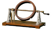
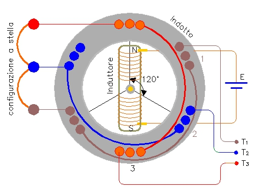
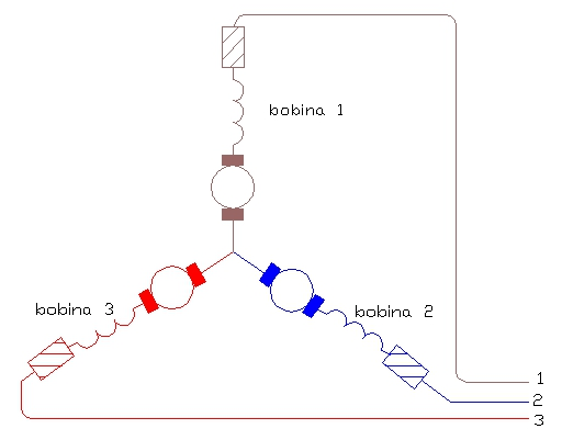
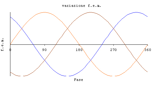
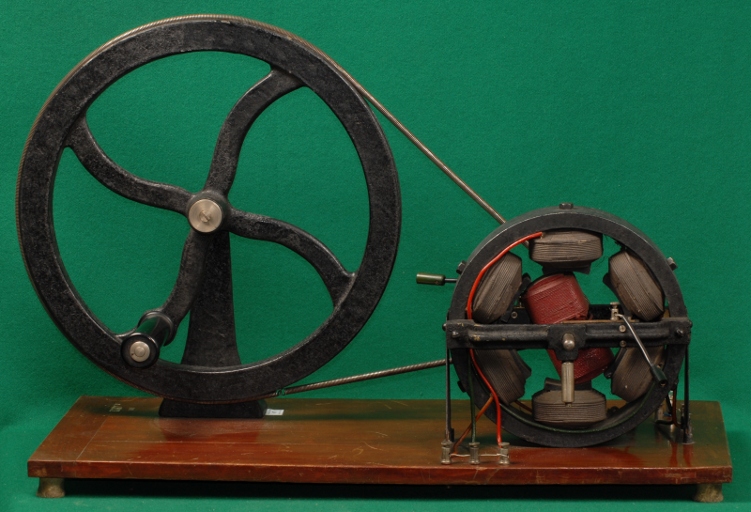
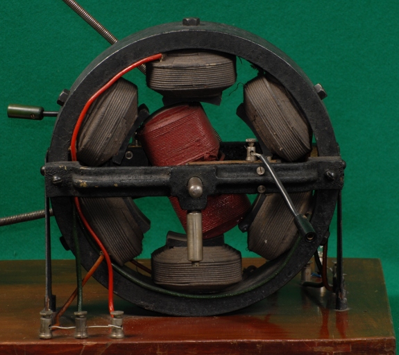
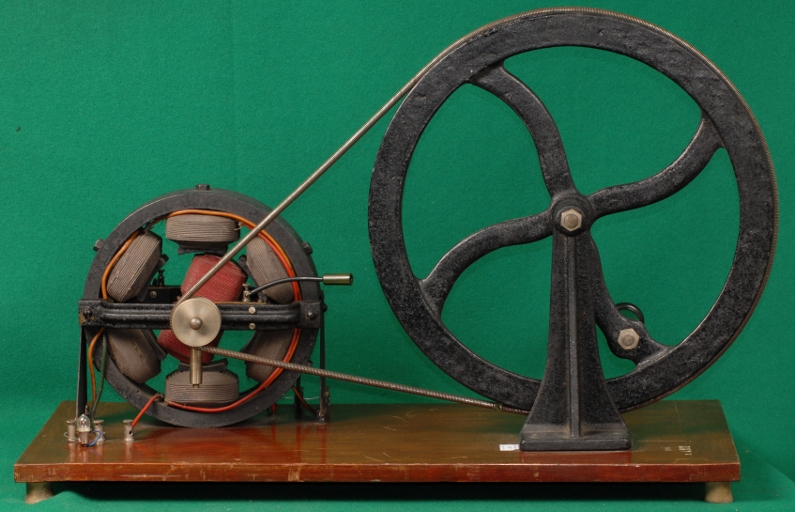
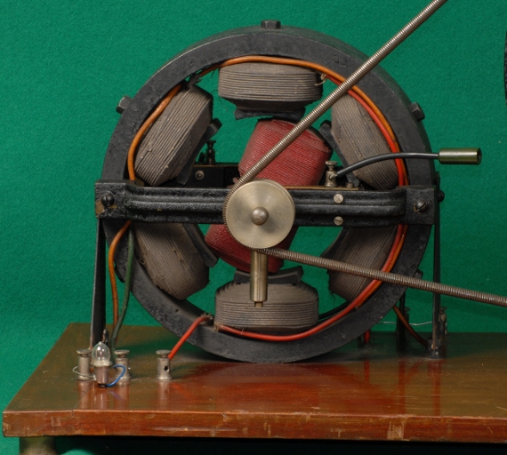
Exhibit 657 is a three-phase alternator activated by hand and mounted on a rectangular wood base supported by four rubber feet. On one side of the axis there is a pulley and a round belt attached to a manually operated flywheel. On the other side (handle side with spinner) there is a heavy iron ring of soft iron acting as a stator (see photo 1). Inside the ring there are six coils wound with visible wires of red, orange and green colors. Each coil is connected in series to the opposite coil and has a resistance of one Ohm. Each pair of coils is connected to a terminal on the handle side and all these terminals are connected in a star configuration. The other ends of the coils are connected to terminals on the pulley side for connection to loads.Inside the ring there is an axis carrying a coil wound on a soft iron cylinder acting as rotor. The ends of this coil can be put in contact with an external emf through metal strips that slide on collars in order to increase the exciting magnetic field. The emf of the three phase alternator is given by: EQ01: [ E_1 = E_0\sin(\omega t) ]. EQ02: [ E_2 = E_0\sin(\omega t+\frac{2\pi}{3}) ]. EQ03: [ E_3 = E_0\sin(\omega t+\frac{4\pi}{3}) ]. where (ω = angular velocity). The voltages of the three phase alternator are illustrated in drawing-3 and are phased by 120°. The advantage of the three-phase system is that the supplied current is constant and the power is never zero.BIBLIOGRAPHY
- [1] Luigi Olivieri, Edoardo Ravelli,"Principi e Applicazioni di Elettrotecnica", Volume Primo. Pag. 250, Cedam Padova 1989.
- [2] URL [ http://www.museoscienza.org/dipartimenti/catalogo_collezioni/scheda_oggetto.asp?idk_in=ST110-00298&arg=Strumentazione%20tecnico%20scientifica ]
Dati Catalografici
| Data di costruzione: | --- |
|---|---|
| Data di carico: | 1939-02-02 |
| Nr. Inventario: | 4902 (Generale dal 1874) |
| Costruttore: | S.I.A.S. |
| Materiale: | rame, ghisa, legno, metallo |
| Dimensioni: | 60 cm x 30 cm x 41 cm |
| Conservazione: | buono (L'apparecchio è funzionante.) |
